KiCad fills copper areas from BRD-files differently than Eagle

Bug #1817312 reported by Ortwin Bönhold
6
This bug affects 1 person
Affects Status Importance Assigned to Milestone
KiCad
Fix Committed
Low
Seth Hillbrand

Bug Description

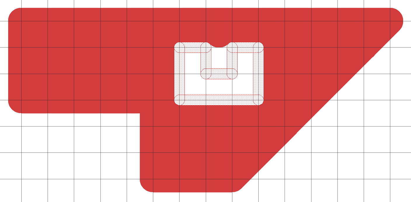
When filling a copper area in Eagle, the line width the copper area is drawn with is taken into account so the filled area is bigger than the drawn polygon by the radius of the line used to draw it (in all directions).

When I import the board-file into KiCad, as far as I can tell the line used to draw the copper area has no line width and thus the middle of the polygon line is taken as outer contour when calculating the fill. This leads to ugly areas different than what my customers tried to make.

(I am an absolute beginner in both KiCad and Eagle so my interpretation could be wrong.)

Application: kicad
Version: (5.0.0), release build
Libraries:
    wxWidgets 3.0.3
    libcurl/7.54.1 OpenSSL/1.0.2l zlib/1.2.11 libssh2/1.8.0 nghttp2/1.23.1 librtmp/2.3
Platform: Windows 7 (build 7601, Service Pack 1), 64-bit edition, 64 bit, Little endian, wxMSW
Build Info:
    wxWidgets: 3.0.3 (wchar_t,wx containers,compatible with 2.8)
    Boost: 1.60.0
    OpenCASCADE Community Edition: 6.8.0
    Curl: 7.54.1
    Compiler: GCC 7.1.0 with C++ ABI 1011

Build settings:
    USE_WX_GRAPHICS_CONTEXT=OFF
    USE_WX_OVERLAY=OFF
    KICAD_SCRIPTING=ON
    KICAD_SCRIPTING_MODULES=ON
    KICAD_SCRIPTING_WXPYTHON=ON
    KICAD_SCRIPTING_ACTION_MENU=OFF
    BUILD_GITHUB_PLUGIN=ON
    KICAD_USE_OCE=ON
    KICAD_USE_OCC=OFF
    KICAD_SPICE=ON

Revision history for this message
Ortwin Bönhold (ortwin) wrote :
tags: added: eagle import pcbnew
Revision history for this message
Wayne Stambaugh (stambaughw) wrote :

@Ortwin, are you sure that Eagle zone fills subtract off the zone outline line width when performing fills? This doesn't make any sense to me but it's possible. Anyone else have any Eagle experience that could shed some light on this issue? If this is the case then we should adjust the zone outline accordingly. Also, don't expect Eagle imports to produce identical boards. Eagle has some features that KiCad does not so all imports need to be carefully reviewed.

Changed in kicad:
status: New → Incomplete
Revision history for this message
Ortwin Bönhold (ortwin) wrote :

Not sure I understand you correctly. Eagle zone fill does not subtract by adds the line width by my experience. I'll try to illustrate with example pictures.

Revision history for this message
Ortwin Bönhold (ortwin) wrote :
Revision history for this message
Ortwin Bönhold (ortwin) wrote :

Adding screenshots of KiCad behaviour as well.

Revision history for this message
Ortwin Bönhold (ortwin) wrote :
Revision history for this message
Wayne Stambaugh (stambaughw) wrote :

You images appear to support what I described. It looks like Eagle uses the line thickness to created the inside edge for the zone filling where KiCad doesn't use any zone line thickness. This means that we are off by 1/2 the zone line thickness when importing Eagle boards. That being said, no one else has filed a bug report on this so I am suspicious that there may be an option setting in Eagle that defines if the zone fill uses the line segment width or not so we should proceed with caution here.

Revision history for this message
Ortwin Bönhold (ortwin) wrote :

I have tried this with our workplace Eagle 9.2.2 as well as a fresh unconfigured Eagle 6.6.0 and both behave the same way. I have had a few customer layouts that obviously expected the Eagle behaviour because the output in KiCad had anomalies while in Eagle it looked more sane. I do however agree that somebody with deeper understanding of these tools should take a look as well.

Revision history for this message
Seth Hillbrand (sethh) wrote :

@Ortwin-

Can you show the expected effect of the different width settings in Eagle? Say make a square polygon fill with two different widths and show what they look like when filled?

Also, it would be helpful to see what a cutout looks like (I think that this is one of the Restrict layers in Eagle) with different widths. Is it the filled polygon width or the cutout width that is the defining value here?

Revision history for this message
Ortwin Bönhold (ortwin) wrote :

Here are some example pictures.

Revision history for this message
Ortwin Bönhold (ortwin) wrote :
Revision history for this message
Ortwin Bönhold (ortwin) wrote :
Revision history for this message
Ortwin Bönhold (ortwin) wrote :
Revision history for this message
Ortwin Bönhold (ortwin) wrote :
Revision history for this message
Ortwin Bönhold (ortwin) wrote :
Revision history for this message
Seth Hillbrand (sethh) wrote :

Perfect. Thank you very much for the details. We'll get this adjusting in v6.

Changed in kicad:
status: Incomplete → Triaged
importance: Undecided → Low
milestone: none → 6.0.0-rc1
Revision history for this message
KiCad Janitor (kicad-janitor) wrote :

Fixed in revision 490c805319974ec84a8fbe8b10e9b59b9a3922a6
https://git.launchpad.net/kicad/patch/?id=490c805319974ec84a8fbe8b10e9b59b9a3922a6

Changed in kicad:
status: Triaged → Fix Committed
assignee: nobody → Seth Hillbrand (sethh)
To post a comment you must log in.
This report contains Public information  
Everyone can see this information.

Other bug subscribers

Remote bug watches

Bug watches keep track of this bug in other bug trackers.